Adding a digi interface to your uBitx Radio by the HF digiBox module
We previously have a digi mode add-on board for uBitx, with the board, you could operate amateur radio digital modes with uBitx. But, recently, due to the global chip shortage, the USB isolation chip ADUM4160 is hardly to source, so the original add-on board is now is discontinued.
The HF digiBox is our new product,it is the replacement of our previous uBitx add-on board. The following info will describe how to add the HF digiBox to the uBitx radio.
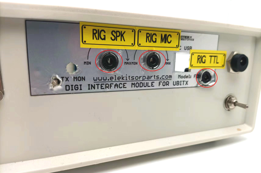
- 1.Drill 3 holes of 8mm (diameter) on your radio’s rear panel.
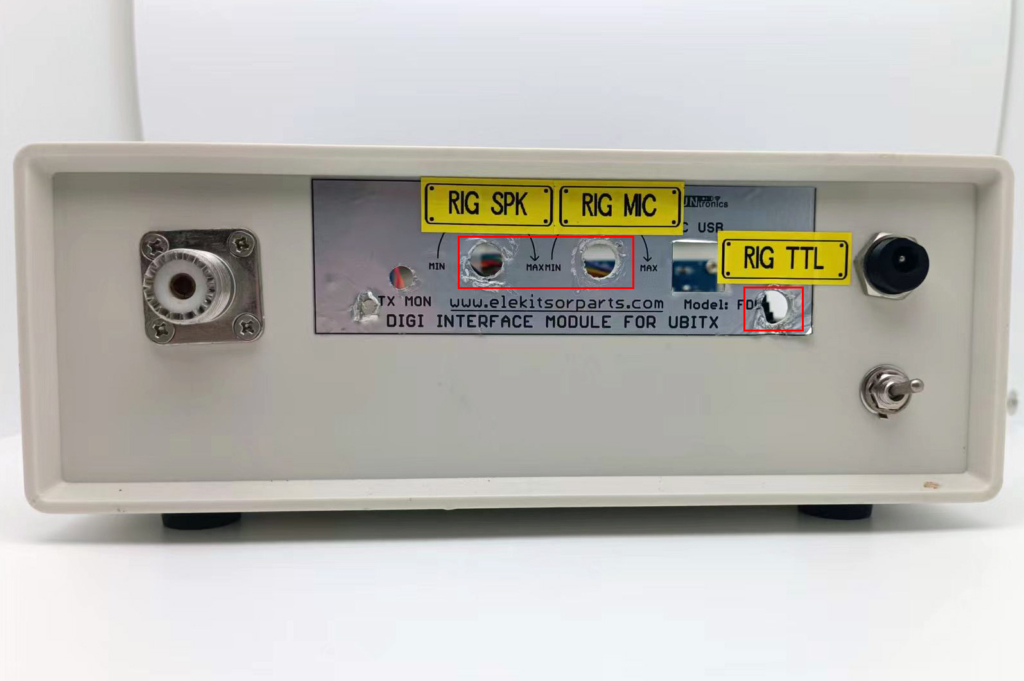
- Install the supplied 3 x 3.5mm stereo jack.
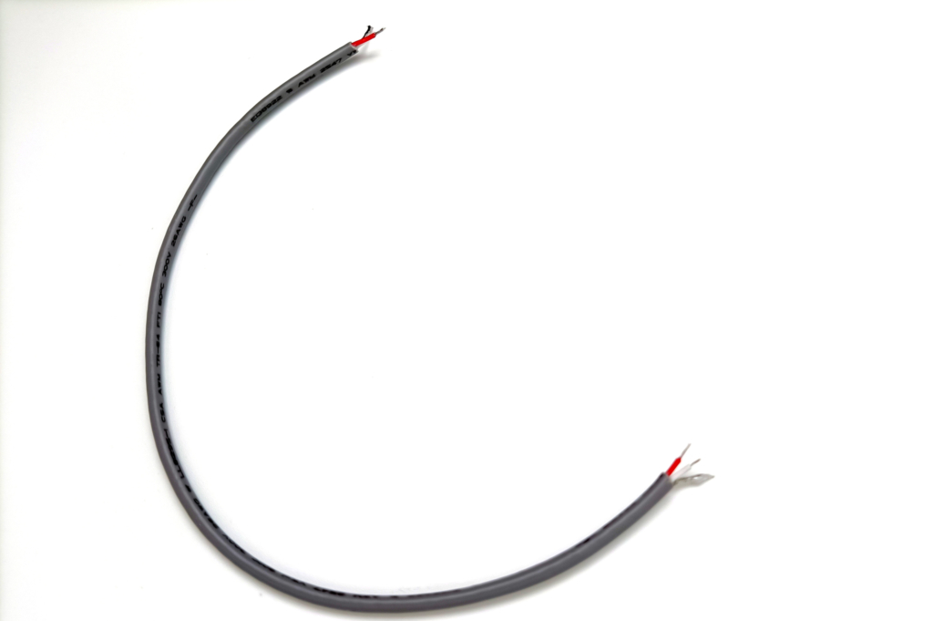
- Strip off the two ends of the supplied 3-pin cable and have them tinned.
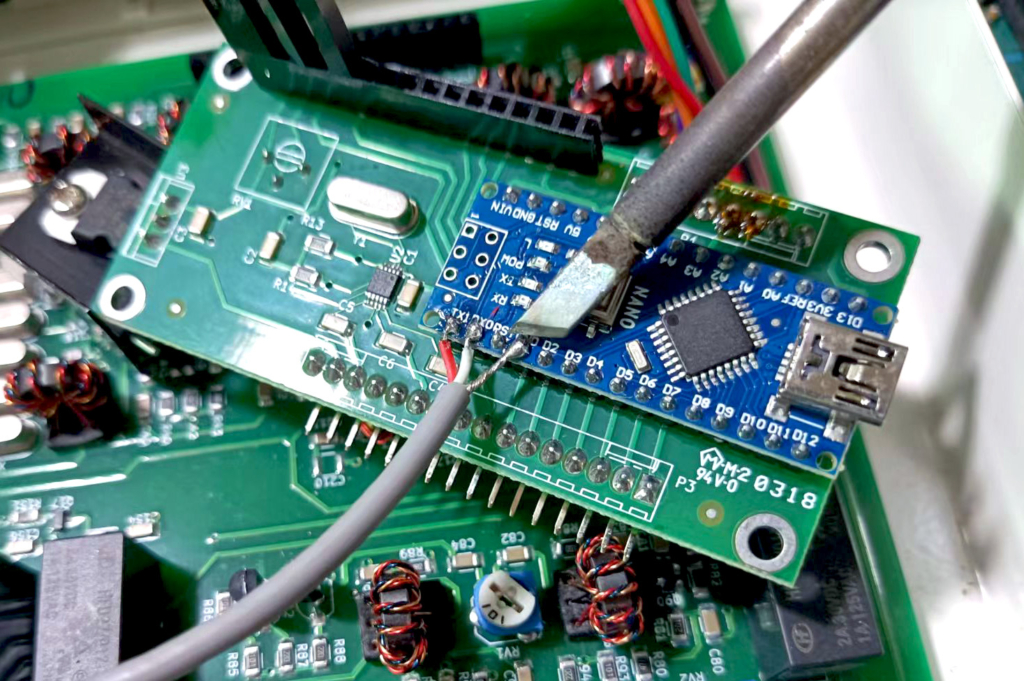
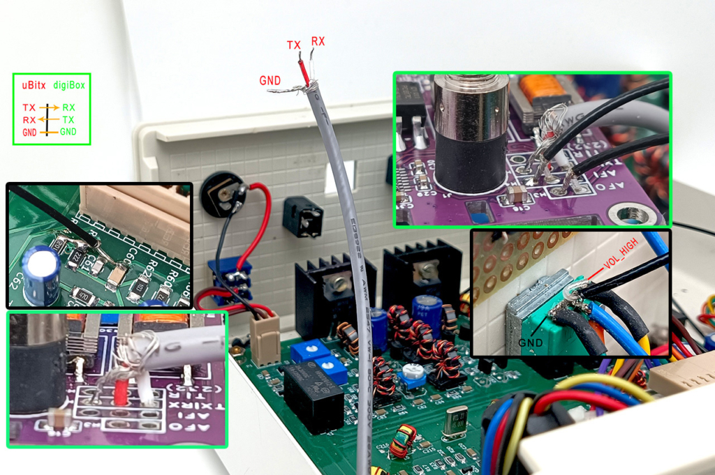
- Open your uBitx, remove the display module from the main board. Solder one end of this cable to Arduino Nano controller board, with the RED wire to TXD, the WHITE wire to RXD, and the shield wire to GND. Next, install the display module back.
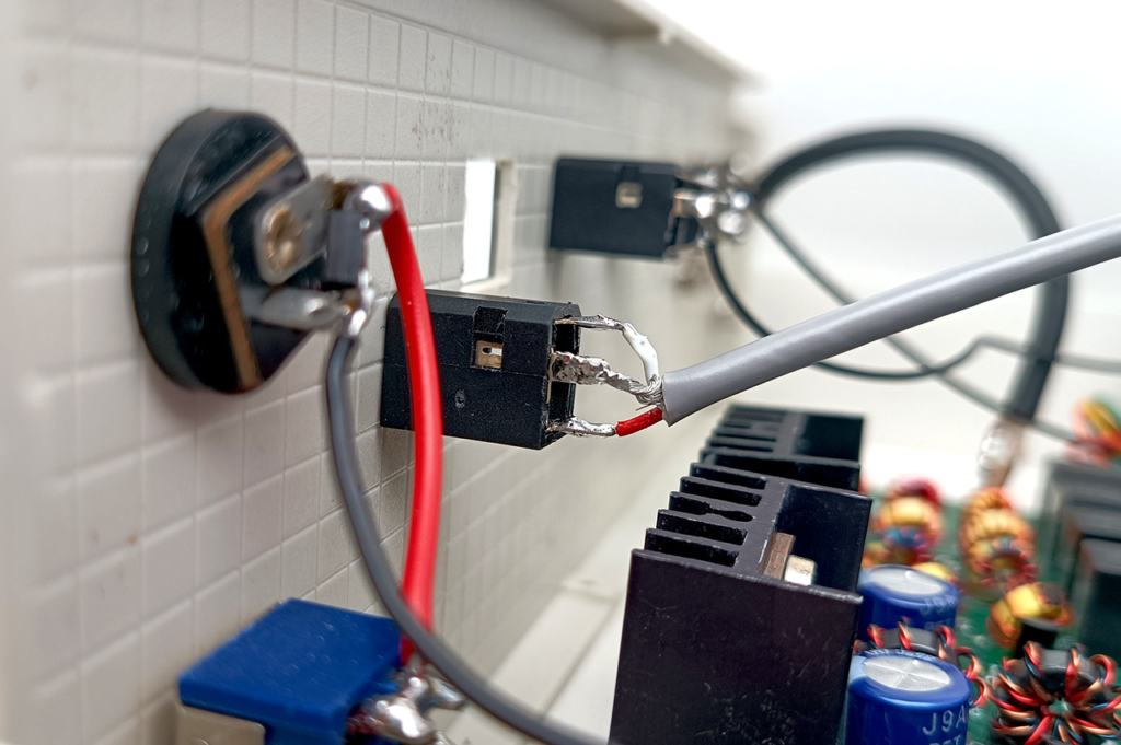
- Now, solder the other end to the previously installed 3.5mm stereo jack, and you have to solder the wires as the picture shows below, if mistakes on the wire sequence made while soldering, the CAT connection will not work.
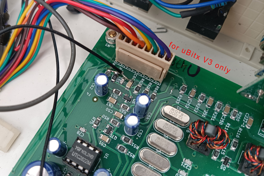
- It’s time to wire the Audio IN and OUT signal to the board. Till now, there are several generation of uBitx radio, from V1 to V6. As I only have a V3 here at hand, so all the info below are based on uBitx V3. For uBitx other than V3, the modification principle is the same, that is “WIRE THE SPEAKER OUT SIGNAL TO the digiBox’s AUDIO IN, AND WIRE THE SIGNAL OF MIC IN ON YOUR RADIO TO the digBox’s AUDIO OUT. ” The schematic below is my way of modification on my uBitx V3.
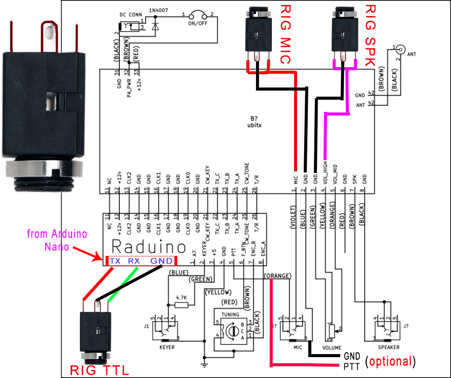
- This is the MIC IN signal on uBitx, we need to wire it out to HF digiBox’s Audio OUT. Please note that the wiring scheme here is only for uBitx V3. It may not be applicable for your uBitx.
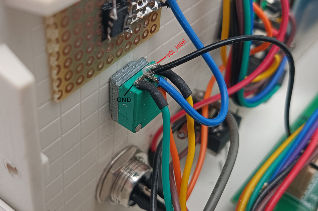
- Here I use the VOL_HIGH signal as the Speaker OUT, but you can also use the phone port(3.5mm jack) as the Speaker OUT.
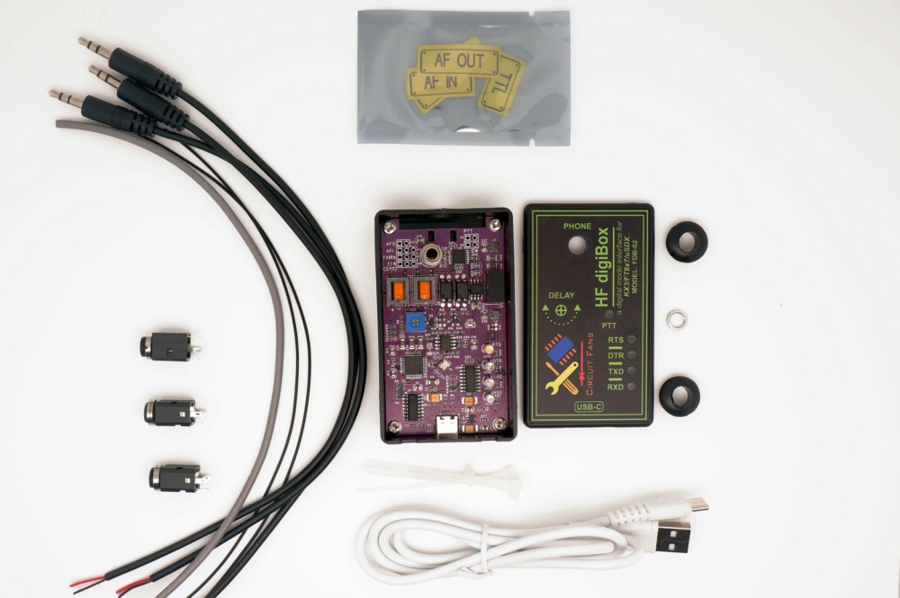
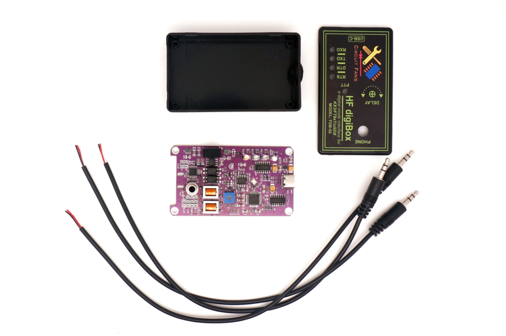
- Now take the interface kit out.
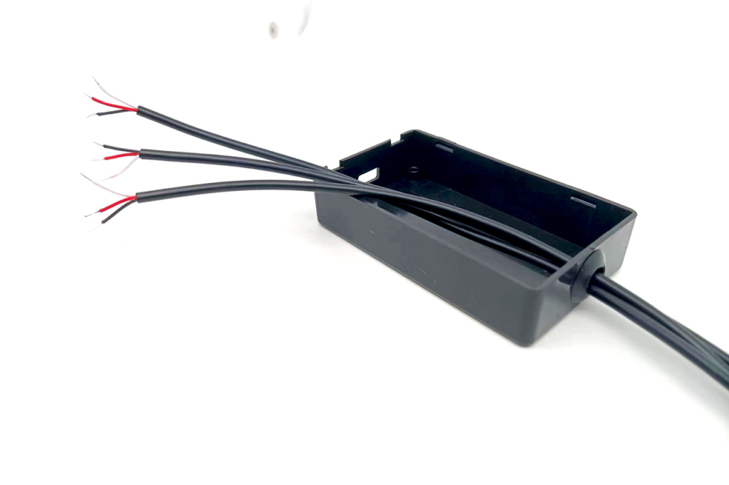
- Let the 3 supplied stereo cables go through the big hole on the enclosure, as it shows on the picture below.
- Here we have 3 cables, two are used for Audio, and one is for CAT or TTL.
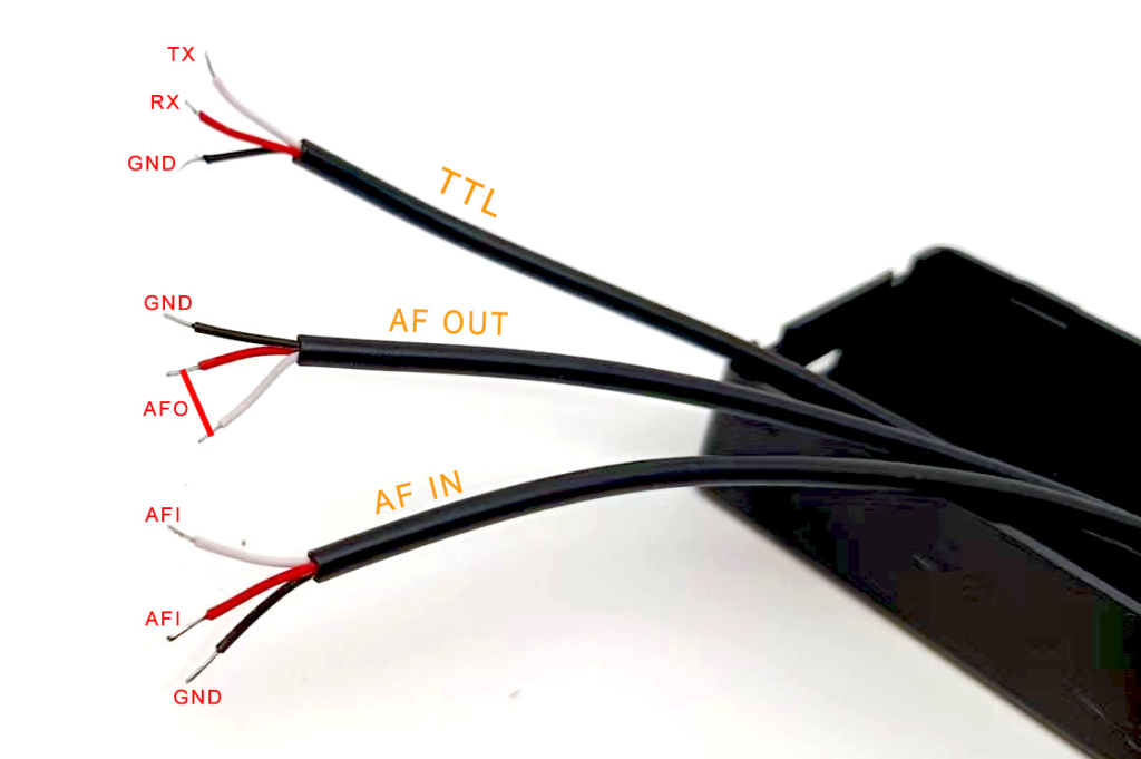
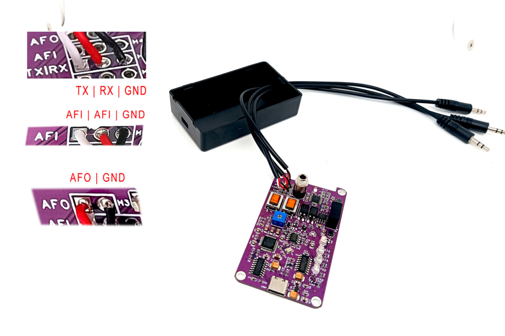
- The cable labeled TTL should be connected to TX|RX|GND, AF OUT is connected to AFO|GND, AF IN is connected to AFI | GND. Please solder the wires as illustrated on the picture below. Pay attention to the wire colors, do not make mistakes while soldering.
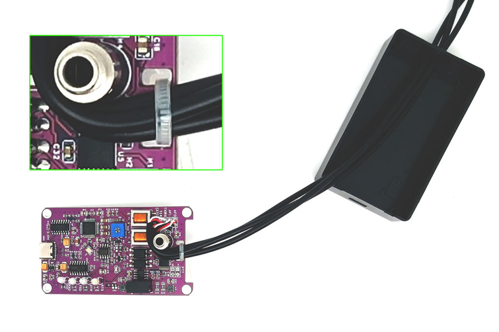
- Next, use a cable tie to fix the three cables in place.
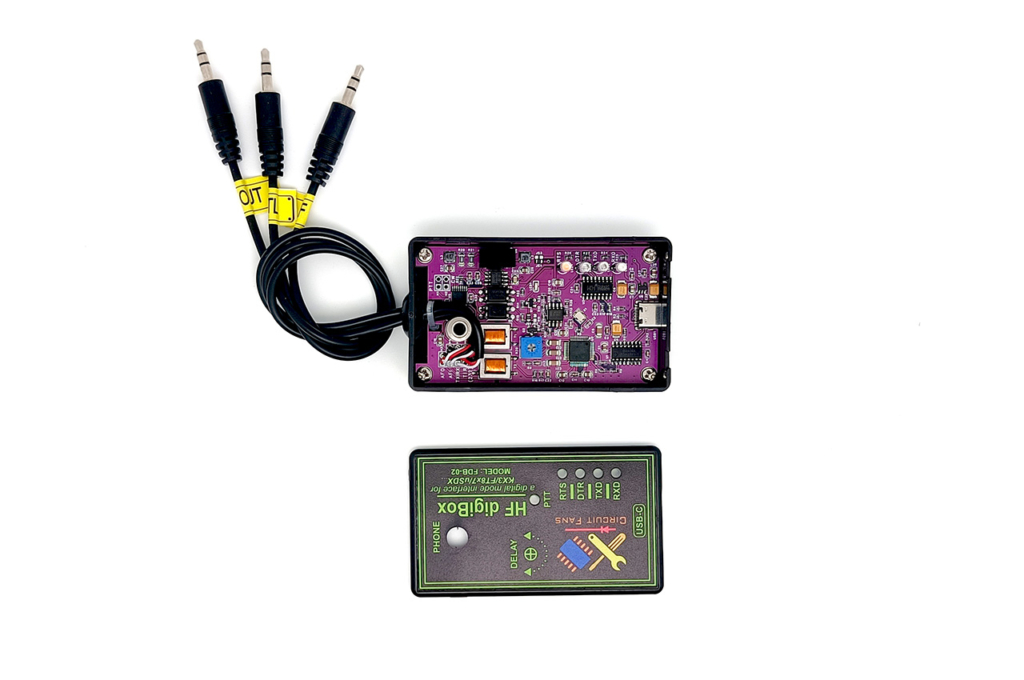
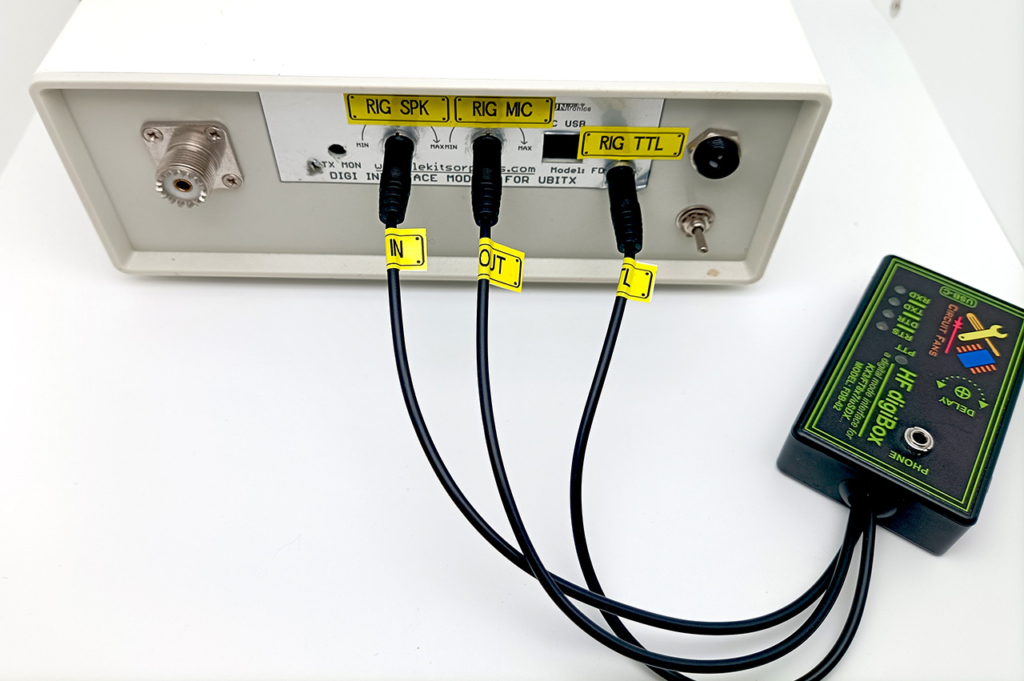
- Now install the board onto the box, fix it with 4 screws, then label the cables as AF OUT, AF IN and TTL.
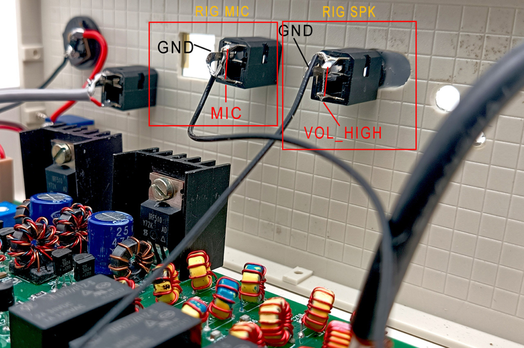
- For operation, just connect the cable AF IN to your rig’s SPK, and AF OUT to your rig’s MIC, and TTL to your rig’s CAT TTL port.
- Due to the small size of the interface board, it is possible to put the the board inside of your uBitx, the scheme of wire connections is the same.
Note: We don’t wire out the PTT and the CW signal in the modification above. So, do not forget to set the PTT triggering to the method of CAT in your application software, or you can wire these two signals out later, then you can set the PTT triggering to DTR and CW to RTS.