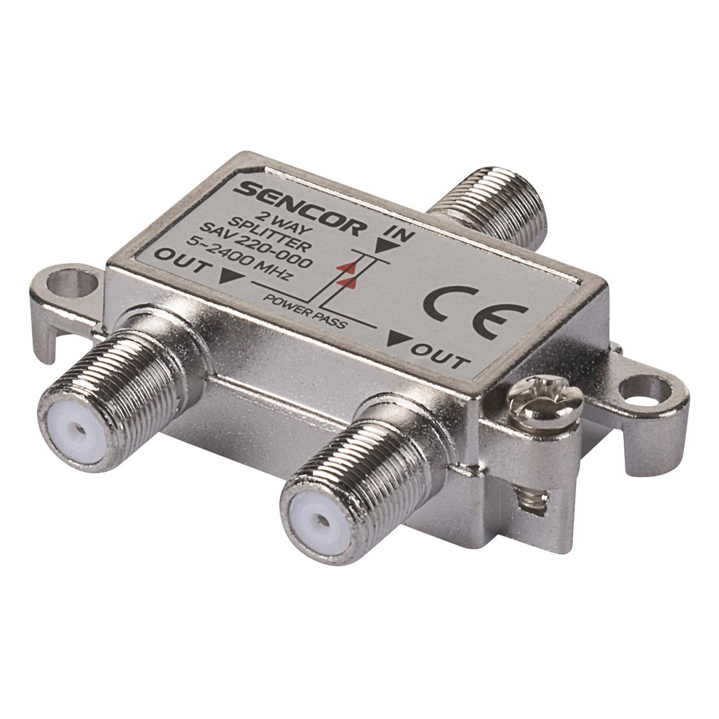
We could get some hints from the name of RF Power Splitters/Dividers and Combiners that they are used to split a single RF line into more than one line and divide the RF POWER, and surely RF combiners are used to combine more than one feed line (coax line) into a single one.
Normally, the RF power combiners and RF splitters are the same items. The circuits on RF combiners and splitters are reversable, that says one circuit can be used to combine and split RF power. In the case of the RF splitter, the RF power is applied to one port and extracted from other multiple ports. Because the RF power is divided or extracted to other ports, the energy from one of the multiple output port is less than the single coming port. As for the combiner, the IN and OUT ports are reversed. Ideally, for both splitters and combiners, the energy from IN and OUT ports should be equal.
There are Two major RF Splitters:
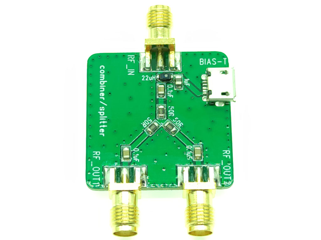
Resistive Power Splitters: Just as the name, power splitters and combiners in this kind use resistors. The use of resistors is to maintain the characteristic impedance of the system, but it introduces loss during any splitting action. However, they are cheap and easy to make.
Hybrid Power Splitters: Unlike the resistive power splitters, the hybrid splitters are expensive. Most hybrid splitters use transformers as the core, and they could keep the loss to the lowest level. Although there are some physical losses in the transformer, the major “loss” is that arising from the splitting process as the same signal is shared between a number of outputs.
About the Loss:
Insertion Loss: When a splitter is inserted into a circuit, there are naturally some losses resulting from the fact that no component is perfectly lossless. These losses are generally minimized and cannot be calculated exactly.
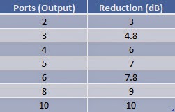
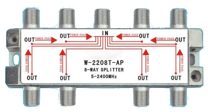
Shared “Loss”: However there are also “losses” resulting from the fact that the signal is being divided between several outputs. This should more accurately be described as a division signal reduction as none of the signal is actually lost. Instead there is a level reduction from the fact that the input power is being shared amongst several outputs.