
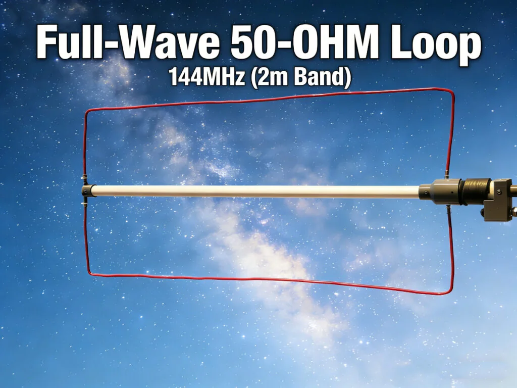
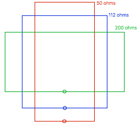
The full-wave loop antenna stands as a fascinating and effective alternative to the ubiquitous dipole, offering desirable characteristics such as gain of approximately 2dB over a dipole, a typically lower noise floor, and a closed-loop radiation pattern. Traditionally, a square or circular full-wave loop presents a feed point impedance in the range of 100-120 ohms, necessitating the use of a quarter-wave matching section (like a 75-ohm coax stub) to interface with common 50-ohm transceivers. However, a clever modification to the antenna’s geometry can dramatically alter this characteristic: by transforming the loop from a square into a rectangle with an approximate 2:1 aspect ratio, and feeding it on the shorter side, the feed point impedance naturally drops to nearly 50 ohms, allowing for direct connection to your radio without additional matching networks. However, a RF choke balun is still needed to choke out the current on the coax braid. See the picture below for the relative shapes of rectangular full wave loops for common feed point impedances(picture from practicalantennas.com). You can go into the depths of a full wave loop by reading this article.
The antenna itself is quite simple and easy to build, consisting of a piece of copper wire forming the radiator and a choke balun. My consideration is just as the followings:
For 2m FM (Vertical Polarization) at 146.00 MHz
Since FM requires vertical polarization, you must feed a vertical wire. To get 50 ohms, that vertical wire must be the short side. Therefore, you build a “Landscape” (Wide) rectangle.
- Orientation: Wide Rectangle (Landscape)
- Long Sides (Top/Bottom): 27.5 inches (69 cm)
- Short Sides (Left/Right): 13.75 inches (33 cm)
- Feed Point: Center of one of the vertical (short) sides
- Impedance: ~50 ohms
For 2m SSB/CW (Horizontal Polarization)
If you want to use this for SSB (weak signal DX), you need horizontal polarization. You must feed the bottom horizontal wire. To get 50 ohm, that bottom wire must be the short side. Therefore, you build a “Portrait” (Tall) rectangle.
- Orientation: Tall Rectangle (Portrait)
- Long Sides (Top/Bottom): 27.5 inches (69 cm)
- Short Sides (Left/Right): 13.75 inches (33 cm)
- Feed Point: Center of the bottom (short) wire
- Impedance: ~50 ohms
Choke Balun Consideration
On a 32mm (1¼ inch) form, 8 turns creates a trap resonant at ~142 MHz. Since we want 146 MHz (a slightly higher frequency), we need slightly less inductance. Removing one turn (going to 7) or spacing 8 turns slightly apart will hit the 146 MHz sweet spot where the choking impedance is highest.
The Final Build
The antenna is quite simple, it mainly consists of two parts, a wire loop that is shaped in rectangle and a choke balun which is coiled from a piece of RG58U coax (0.95m) on a 32mm PVC pipe (70mm). In order to make it a better looking, I designed the choke balun and the antenna wire support by Fusion360. Besides with the 3d printed parts, some other things are needed for this project, see the table below.
| Name | Quantity or Length | Note |
| (D-32mm) PVC pipe | 70mm | As the coil form |
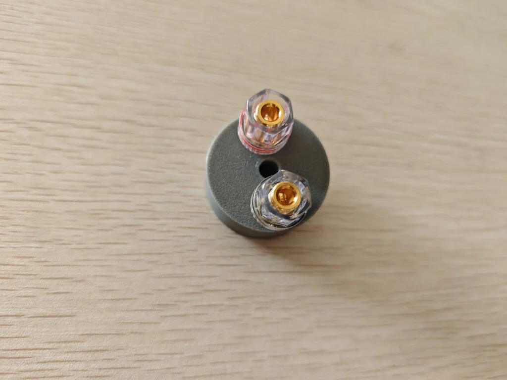
| Binding posts | 2 | Connecting the antenna wire |
| RG-58U coax | 0.95m | Choke balun |
| Plastic coated copper wire (with 2mm inner conductor) | 2.04m | Antenna wire |
| U-shape wire lug (UT2.5-6) | 2 | Soldered on the antenna wire |
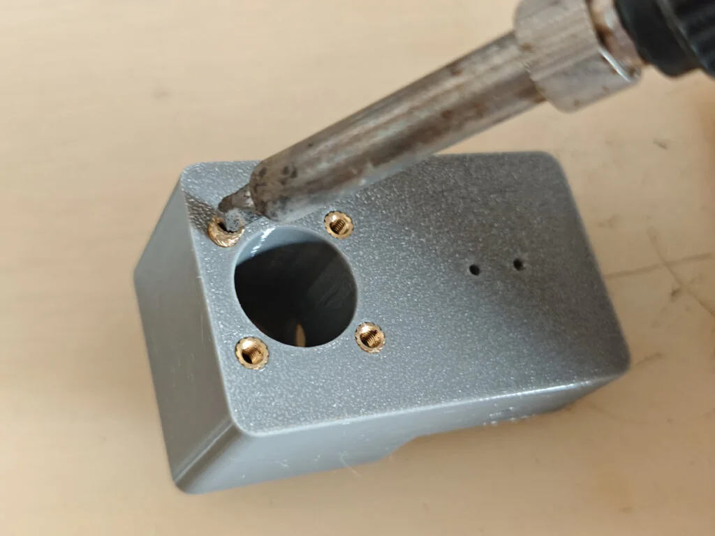
| M3 x 6 brass heat insert nuts | 4 | Will be implanted into the 3d printed antenna base |
| N type female chassis mount connector | 1 | |
| M3 x 6 head-sink screws | 4 | Mounting the N type UHF connector |
| M3 x 10 self-tapping screws | some | |
| Short cable ties | some |
The pictures below will explain how to build the antenna:
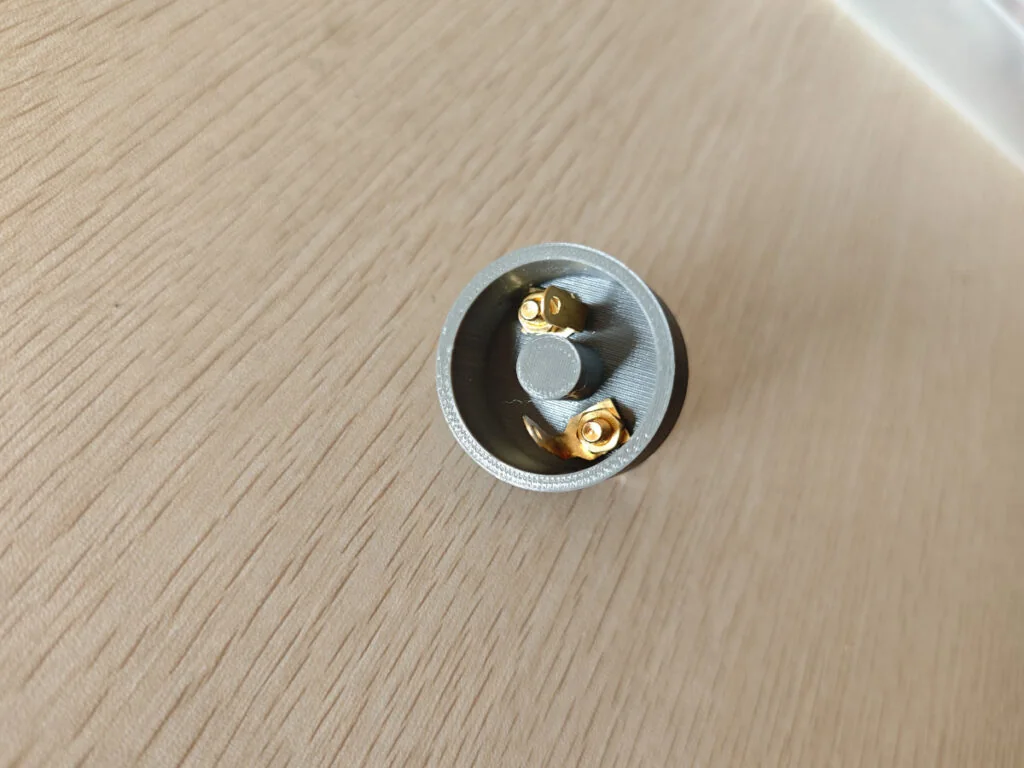
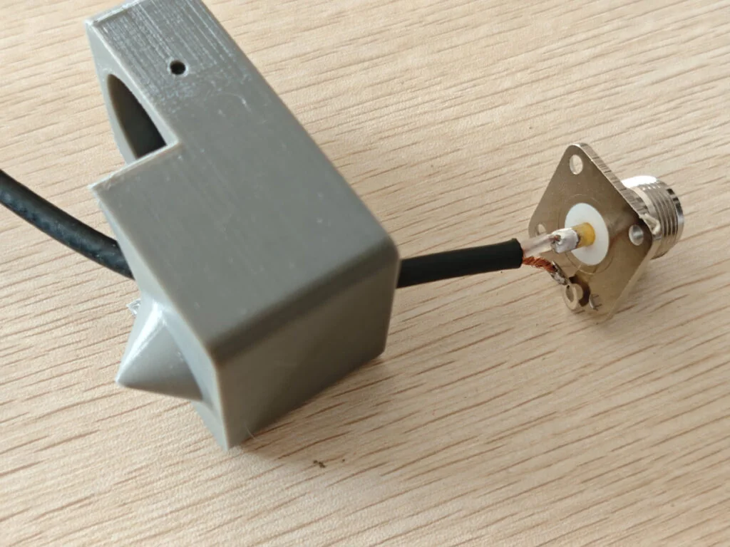
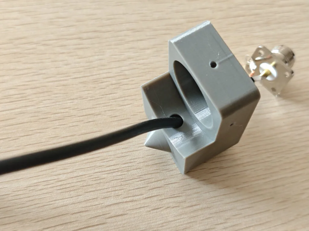
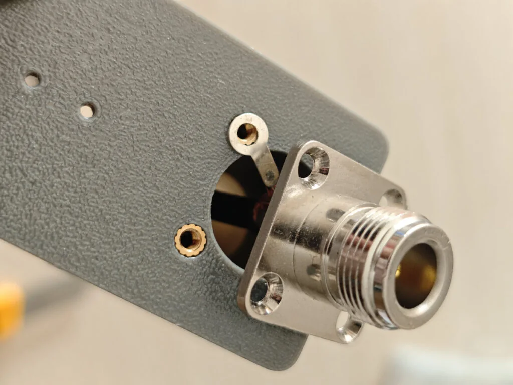
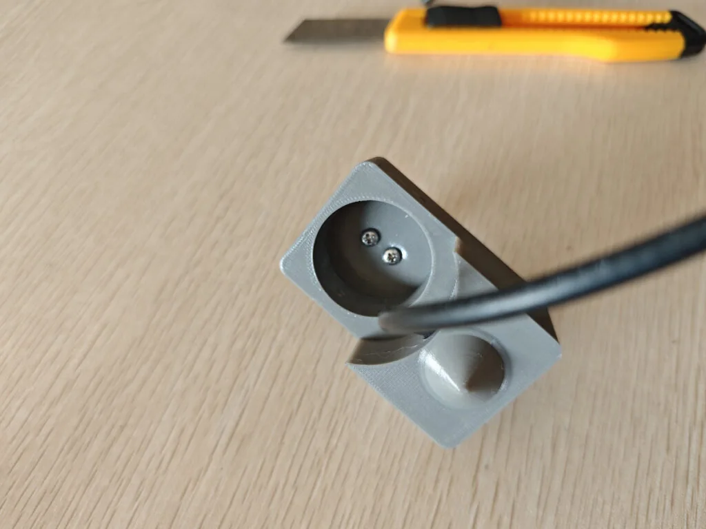
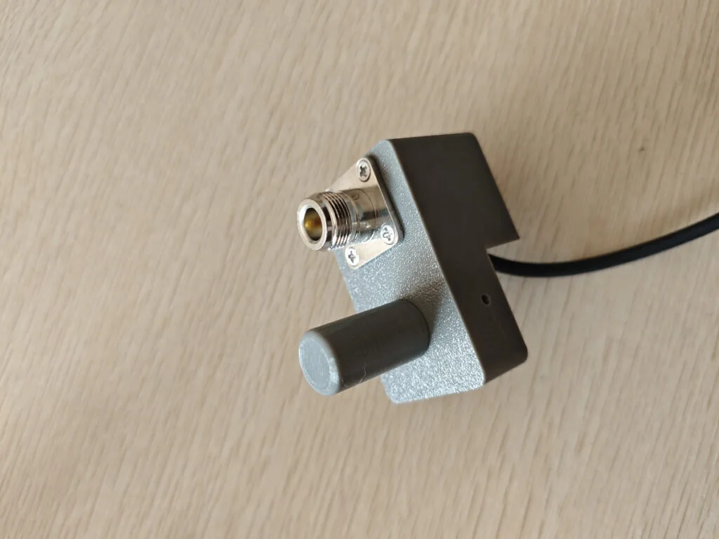
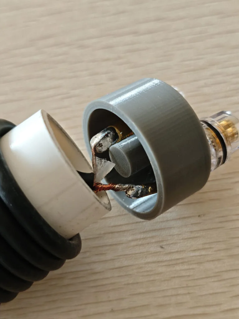
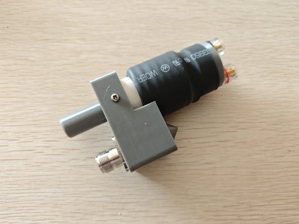
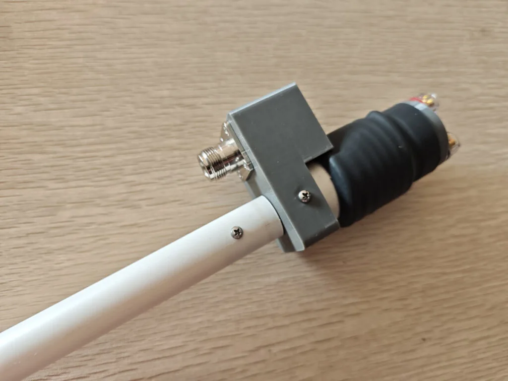
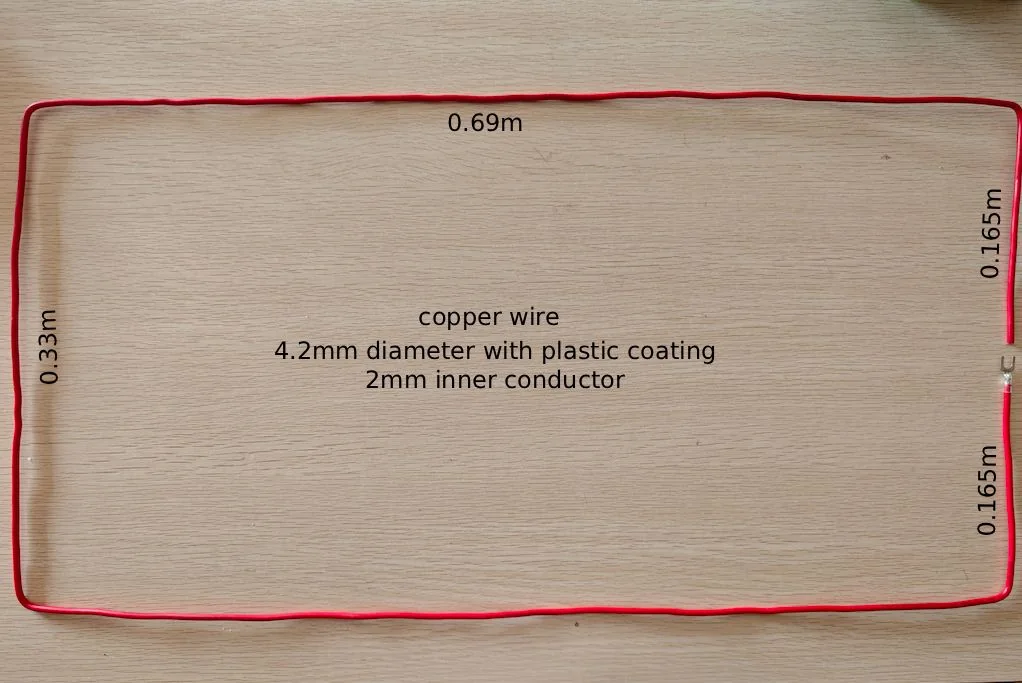
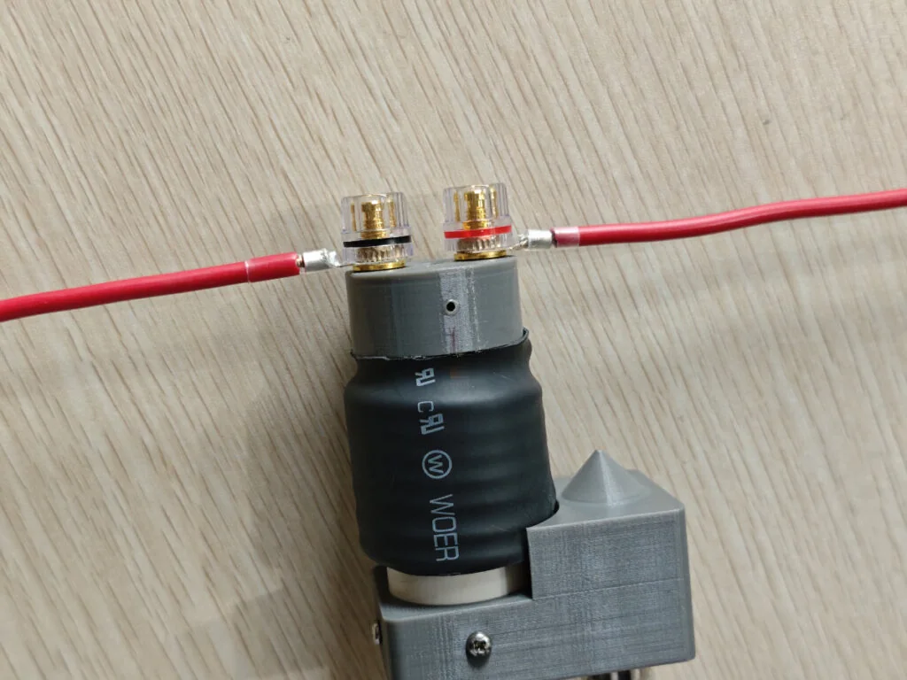
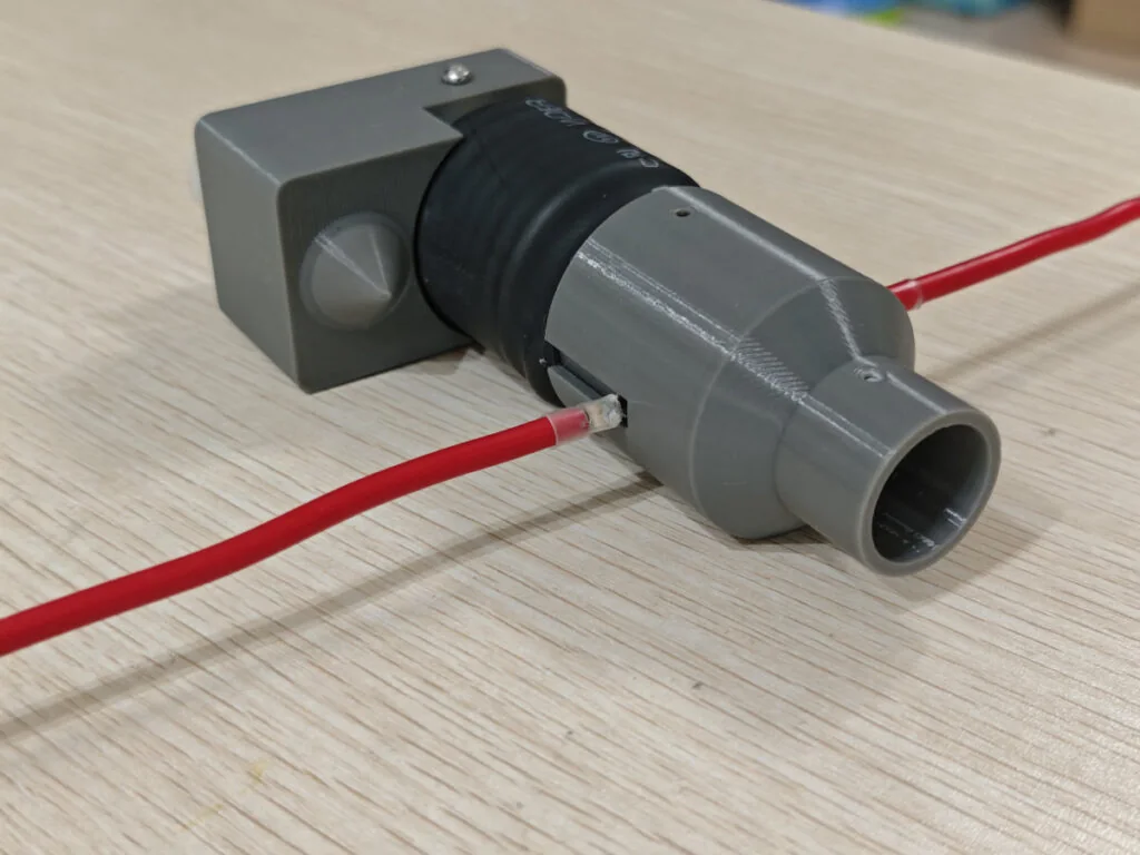
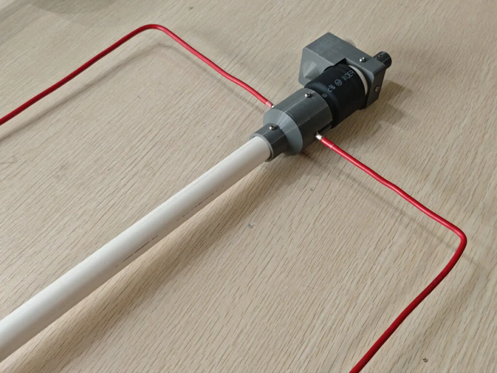
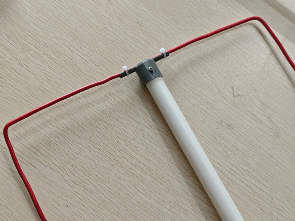
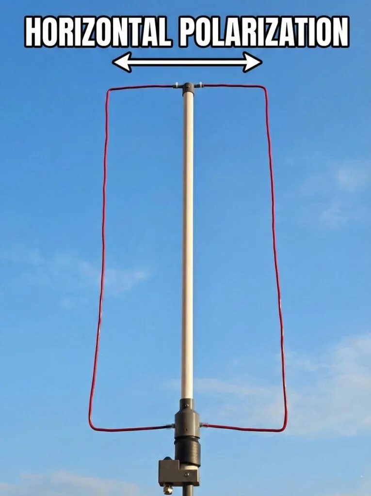
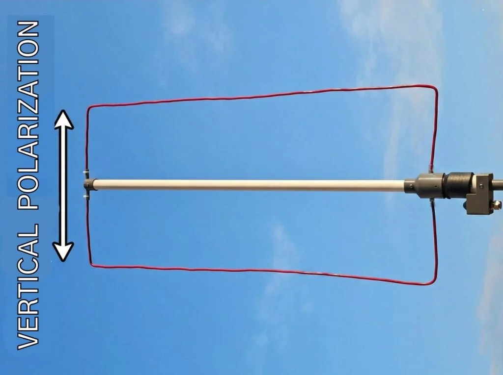
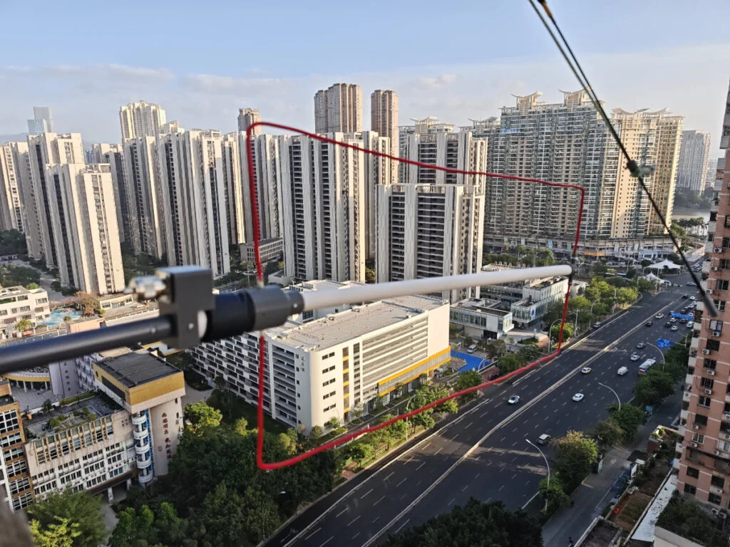
The antenna was mounted on the balcony, about 60m above the ground, working in vertical polarization for the APRS radio.
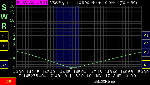
The SWR plot shows the antenna resonates at 145.275 with the real resistance of 48.1 ohms. It has a wide bandwidth, from 142MHz to 149MHz, within swr 2.0.
Project Files:
https://drive.google.com/file/d/1UsUHh–u7xS6wJbDV4vmFz-QHB5T1pDI/view?usp=sharing