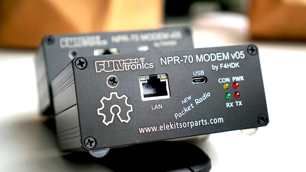
This NPR-70 Modem Kit Assembly Guide is a web version of the original ELEKITSORPARTS PDF manual. It is intended for users assembling or servicing the NPR-70 v05 kit, and it keeps the original PDF available as a download.
Related product: NPR-70 v05 Modem, factory-assembled version.
Download the original NPR-70 Modem Kit Assembly Guide PDF.
About NPR-70
NPR-70 is a New Packet Radio modem originally designed by F4HDK. The project is open source and was published on Hackaday. It provides bidirectional IP data transmission over the 70 cm amateur band and can be useful for Hamnet extension, DX spot access, and field data links.
The v05 hardware adds onboard SPI SRAM to improve transmit performance. Keep the modem firmware updated before relying on the external SRAM support.
Tools Recommended
- Fine-tip temperature-controlled ESD-safe soldering station.
- High-power soldering iron or gun for the BNC/SMA ground-connected parts.
- Small-diameter electronics solder.
- Small Phillips screwdriver.
- Needle-nose pliers and small cutters.
- Digital multimeter for voltage checks.
- Magnifier or hands-free inspection lens.
- ESD wrist strap and anti-static mat when handling boards and modules.
Assembly Overview
The kit assembly has two main stages: soldering the modules and through-hole parts, then mounting the completed modem board into the enclosure. Most SMD parts are factory assembled, so the user mainly installs modules, headers, regulators, ports, wiring, jumpers, and enclosure hardware.
Step 1: RF Module
Start with the RF4463F30 module. Tin one corner pad, align the module using the corner marks on the PCB and module, solder the first pin to hold position, then solder the ground-connected pins with enough heat for full solder flow. Inspect the module carefully before moving on.
Step 2: LM2596 Power Module
Break the 4-pin header into individual pins, solder them to the LM2596 module, then apply a 12 V DC source to the input. Use a digital voltmeter on the output and adjust the module potentiometer until the output is 6.5 V. After adjustment, install and solder the module to the main PCB.
Step 3: W5500 And STM32 Modules
Install the W5500 Lite module and the pin headers for the STM32L432KC module. ELEKITSORPARTS preconfigured the important STM32 solder jumpers before shipment, but the SB9 jumper determines whether the modem works in normal mode or remotely manageable mode. Refer to the F4HDK NPR documentation before changing that jumper.
Step 4: LEDs, Regulators, And RF Connector
Install the LED modules with correct color orientation, then install the L4940 5 V and LM2937 3.3 V regulators. Install the right-angle RF connector with enough heat on the ground pins, because those pads are connected to larger copper areas.
Step 5: DC Port, Toggle Switch, And Wiring
Install the DC port and toggle switch according to the wiring diagram in the original PDF. After wiring, apply 12 V DC and switch on the modem. The PWR LED should remain on. CON and RX may flash during startup, then turn off along with TX. If the LEDs do not behave as expected, inspect the previous steps before continuing.
Power Jumper Options
NPR-70 v05 has four power jumpers that select the input voltage path.
| Power option | Solder | Leave open | Note |
|---|---|---|---|
| 12 V DC | SB1, SB3 | SB2, SB4 | Default for factory-assembled units. |
| 6 V DC | SB2, SB3 | SB1, SB4 | Use only when your power setup requires it. |
| 5 V DC | SB2, SB4 | SB1, SB3 | Use only when your power setup requires it. |
Firmware Update Note
For firmware updates, visit the F4HDK NPR-70 project page and download the current firmware. With the modem powered and connected by Micro-USB, the STM32 board appears as a storage device. Copy the firmware file to that drive, then disconnect USB and switch the modem off.
Enclosure Assembly
Attach the M3 copper posts to the PCB, install the board into the lower enclosure using the wall slots, fit the rear panel, and secure the DC port, toggle switch, and RF connector. Then install the front panel, secure the regulator heat sinks, fasten the board to the lower cover, fit the top cover, and apply the rubber feet.
Final Setup
After assembly, configure the modem as MASTER or CLIENT according to the F4HDK documentation. Start with the NPR-70 introduction and quick-start guide before changing advanced modem settings.